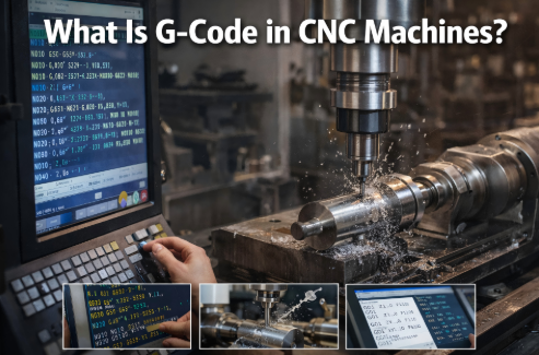
CNC machine code is, in essence, the instruction language that tells a CNC machine how to move, cut, drill, change tools, switch coolant on or off, and end a program. At its core, it comes down to just two parts: G codes control machining actions, while M codes control auxiliary functions. Once you understand that, you already have the foundation of CNC programming.
For manufacturers, engineering teams, purchasing professionals, and even project managers evaluating a supplier’s machining capability, CNC code is not merely an operator-level detail. It directly affects whether the machining path is reasonable, whether dimensions remain stable, whether batch production can be controlled, and whether the equipment and process can truly deliver consistent results.
Many people see CNC code for the first time and think it is just a cold string of letters and numbers. It is not. It is better understood as a highly standardized machining language. When written correctly, the machine runs efficiently, consistently, and repeatably. When written poorly, the result may be an alarm, a crash, scrap, or delivery delays.

1. Basic Understanding of CNC Machine Code
CNC machine code, often referred to as NC code or CNC code, is the standard set of instructions used by a machine tool to perform machining tasks. It is not simply a matter of entering a few commands. It is a programming logic system built around machining actions, coordinate systems, tool paths, and machine control.
In practical use, CNC code serves three core purposes:
1.1 Controlling How the Machine Moves
The machine needs to know where the tool should go, how it should travel, how fast it should move, and how deep it should cut. This part is mainly handled by G codes.
1.2 Controlling When the Machine Performs Supporting Actions
When should the spindle start? When should coolant turn on? When should the program end? These functions are usually controlled by M codes.
1.3 Turning Machining Experience into a Repeatable Program
In batch production, the value of a program is not simply that it can machine a part once. It is that it can execute the same logic, the same path, and the same rhythm over and over again with stability. That is why mature manufacturers place great importance on programming standards, trial runs, and code management.
2. Core Categories and Basic Rules of CNC Code
If you want to understand CNC code, do not rush to memorize an entire code chart. Start by seeing the big picture clearly. Most basic programs, in fact, revolve around just two major types of code.
2.1 The Two Core Code Systems
2.1.1 G Codes: Preparatory Functions
G codes are mainly used to control machining actions and form the core of CNC programming. They determine how the tool moves, whether cutting takes place, and how the machining path is executed.
For example:
- G00: rapid positioning
- G01: linear cutting
- G02: clockwise arc
- G03: counterclockwise arc
- G90: absolute programming
- G91: incremental programming
Put simply, G codes determine how the machining is performed.
2.1.2 M Codes: Auxiliary Functions
M codes are mainly used to control auxiliary machine functions. They do not directly define the cutting path, but the program still cannot run properly without them.
For example:
- M03: spindle clockwise rotation
- M05: spindle stop
- M08: coolant on
- M09: coolant off
- M30: end of program and reset
In other words, M codes determine how the machine’s supporting actions are carried out.
2.2 Basic Rules for Writing Code
CNC code may look short. In practice, though, many problems arise precisely from these seemingly simple rules.
2.2.1 Keep One Logical Action per Line and Maintain Clear Formatting
Although formatting details may vary slightly from one control system to another, the basic principle is clear: each line should express one clear action whenever possible. Letter-number combinations must be accurate. Do not insert meaningless symbols, and do not casually omit key parameters.
2.2.2 You Must Clearly Distinguish Coordinate Directions
If an X, Y, or Z direction is entered incorrectly, the machine will not just move “a little off.” It may move entirely in the wrong direction. On the Z axis in particular, many beginners risk tool crashes because they confuse positive and negative directions.
2.2.3 You Must Distinguish G90 from G91
G90 means absolute programming.
G91 means incremental programming.
These two modes are critical. One uses the origin as the reference. The other uses the previous point as the reference. If the wrong mode is used, the entire tool path can shift, and the error may not be obvious immediately.
2.2.4 The Beginning and End of the Program Must Be Complete
A well-structured program usually starts with a program number, includes a clear work coordinate setup, tool calls, spindle and coolant control, and ends with a definite program-ending command. M30 is commonly used at the end to finish and reset the program.
Leave out one line, and the consequences can be serious.
3. Detailed Explanation of Common G Codes
There are many G codes, but for most basic machining tasks, the ones used most frequently are not especially complicated. It is far more effective to master the common ones first and expand gradually.
3.1 G00: Rapid Positioning
G00 is used for fast tool movement when the tool is not cutting.
Its purpose is not machining. It is to reduce non-cutting travel time and improve cycle efficiency. For example, when the tool moves from a safe position to a point above the workpiece, G00 is commonly used.
That said, G00 does not mean “move quickly however you like.” The path still needs to be safe. In setups with complex fixtures or varying part heights, a poorly planned rapid path can be risky.
3.2 G01: Linear Interpolation
G01 is one of the most commonly used basic cutting commands. It moves the tool in a straight line at a specified feed rate while cutting.
Whether you are milling a flat surface, cutting a slot, tracing an edge, or machining many simple contours, G01 is almost always fundamental. It is usually used together with an F value, which defines the feed rate.
If G00 means “rapid move without cutting,” then G01 means “cut forward at a controlled feed.”
3.3 G02 / G03: Circular Interpolation
G02 indicates clockwise arc cutting.
G03 indicates counterclockwise arc cutting.
These two commands are used to machine arcs, fillets, and curved transitions. They are common in profile parts, cavity parts, circular features, or toolpaths that require smooth transitions.
They are also a common source of errors for beginners. The reason is simple: if the end point, center parameters, or direction is wrong, the machine may alarm or follow an abnormal path.
3.4 G90: Absolute Programming
G90 means that all coordinate values in the program are referenced from the workpiece origin or the current coordinate system origin.
This method is more intuitive, easier to check, and better suited to most part programming and program review. That is why G90 is often the default mode in many practical applications.
3.5 G91: Incremental Programming
G91 means the coordinates in the current command are referenced from the previous position.
It can be useful for repeated step movements, hole patterns, and relative moves. But it is also easier for beginners to confuse. Once there is an error in one step, all following positions may be affected.
So G91 can be used, but it should be used carefully. In batch programs that have not been fully verified, extra caution is necessary.
3.6 G54–G59: Work Coordinate System Setup
G54 through G59 are used to define different work coordinate systems. They are extremely important in actual machining.
In environments with multiple stations, fixtures, or part setups, coordinate system selection almost determines whether the machining reference is reliable. The program itself may be correct, but if the work coordinate system is set incorrectly, dimensions, positions, and hole locations will all shift.
Errors of this kind may look like programming mistakes. In reality, they are often reference-setting mistakes.
3.7 G40 / G41 / G42: Tool Radius Compensation
G40: cancel tool radius compensation
G41: tool radius compensation left
G42: tool radius compensation right
Tool compensation creates an adjustable relationship between the programmed path and the actual tool radius. The benefits are obvious: dimension correction becomes more flexible, less code needs to be rewritten, and batch adjustment becomes more efficient.
It is also one of the most common sources of problems. Compensation direction may be reversed. Compensation values may be entered incorrectly. Compensation may be turned on or off at the wrong point. All of these can cause dimensional errors or even abrupt toolpath changes.
4. Detailed Explanation of Common M Codes
If G codes determine how the tool moves, then M codes determine how the machine’s supporting functions work together. Many beginners focus heavily on G codes and neglect M codes, only to find that the program seems workable in theory but runs poorly in practice.
4.1 M03: Spindle Clockwise Rotation
M03 starts the spindle rotating in the forward direction. It is the most common spindle start command. Most standard milling and drilling operations use it.
It is usually paired with an S value that defines spindle speed. In many programs, the S value is set first, followed by M03.
4.2 M04: Spindle Counterclockwise Rotation
M04 starts the spindle in reverse rotation. It is used less often and usually appears in special processes, with specific tools, or in reverse-cutting situations.
Not every operation requires it, but you should still know what it means.
4.3 M05: Spindle Stop
M05 stops spindle rotation. It is commonly used during tool changes, at the end of machining, or during program shutdown.
The command itself is simple, but it is essential. Many following actions assume that the spindle has already stopped.
4.4 M08: Coolant On
M08 turns coolant on. Its role is not limited to cooling. It also helps with lubrication, chip evacuation, and tool protection.
In many materials and especially in continuous cutting or deep-hole operations, proper coolant use directly affects tool life and surface quality.
4.5 M09: Coolant Off
M09 turns coolant off. It usually appears after machining is complete, during tool retraction, or shortly before the program ends.
Even though it is just an auxiliary command, careless use can create confusion on the shop floor. At best, it wastes coolant. At worst, it affects visibility and maintenance operations.
4.6 M30: End of Program and Reset
M30 is commonly used to end the program and return the machine to a reset state, creating a complete closed loop.
It is one of the most common program-ending commands. Without it, the program may not finish properly as intended.
5. The Complete Workflow for Writing a CNC Program
Program writing is not something to do randomly. A clean, reviewable, and reliable program usually follows a fixed logic.
5.1 Set the Program Number and Work Coordinate System
At the beginning of the program, define the program number and set the coordinate system, such as G54. The focus here is not to start cutting immediately, but to establish the machining reference clearly.
If the reference is wrong, everything that follows is wasted.
5.2 Start the Spindle and Coolant, and Set Cutting Parameters
Based on the tool and material, set spindle speed and feed, then start the spindle and coolant. A common combination is an S value with M03, followed by M08.
This may seem routine, but it actually reflects process capability. Different materials, different tools, and different stock allowances can require very different parameters.
5.3 Rapidly Position the Tool and Enter Machining Readiness
Use G00 to move the tool to a safe and reasonable start position, then prepare to switch into cutting mode.
Do not rush this step. Many collisions happen not during cutting, but before the cut even begins.
5.4 Execute the Cutting Path
Use commands such as G01, G02, and G03 to carry out straight-line cutting, arc cutting, contouring, or other machining actions according to the part geometry.
This is the main body of the program and the part that most strongly reflects programming logic and process experience.
5.5 Retract the Tool and Turn Off Auxiliary Functions After Machining
After cutting is complete, the tool exits the work area, the spindle and coolant are turned off, and the program moves into its closing stage.
When this step is done cleanly, the shop floor runs smoothly. When it is done poorly, the next tool change, setup, or cleanup becomes more difficult.
5.6 End the Program and Reset
Finally, use M30 to end the program and reset the machine. Only then is the full loop of a basic program complete.
6. Simple Practical Example: Basic Linear Machining Program
Below is a very basic example intended to be easy to understand. Different systems, machines, and post-processors may vary in format, but the logic remains the same.
6.1 Sample Program
| Line No. | Code | Description |
|---|---|---|
| 1 | O0001 | Program number |
| 2 | G90 G54 G00 X0 Y0 Z50 | Absolute programming, select G54 workpiece coordinate system, rapid traverse to X0 Y0 Z50 safe position |
| 3 | S1200 M03 | Spindle speed 1200 RPM, spindle clockwise rotation |
| 4 | M08 | Coolant ON |
| 5 | G00 X10 Y10 Z5 | Rapid traverse to 5mm above machining start point |
| 6 | G01 Z-2.0 F100 | Feed to Z-2.0mm depth at 100mm/min feed rate |
| 7 | G01 X60 Y10 F200 | Linear cutting to X60 Y10 at 200mm/min feed rate |
| 8 | G00 Z50 | Rapid retract to Z50 safe height |
| 9 | M09 | Coolant OFF |
| 10 | M05 | Spindle stop |
| 11 | M30 | Program end and reset |
6.2 Program Explanation
O0001
Program number.
G90 G54 G00 X0 Y0 Z50
Use absolute programming, call the G54 work coordinate system, and rapidly move the tool to a safe position.
S1200 M03
Set spindle speed to 1200 and start the spindle rotating clockwise.
M08
Turn coolant on.
G00 X10 Y10 Z5
Rapidly move the tool to the start point above the workpiece.
G01 Z-2.0 F100
Feed the tool down to Z-2.0.
G01 X60 Y10 F200
Cut in a straight line to the target position.
G00 Z50
Rapidly retract the tool to a safe height.
M09
Turn coolant off.
M05
Stop the spindle.
M30
End the program and reset.
This program is not complicated. That is precisely why it is so useful for beginners. It helps build the basic logic of coordinates, tool entry, cutting, retraction, and program closure.
7. Key Mistakes to Avoid in CNC Code Writing and Operation
The biggest risks in CNC programming do not always come from complex programs. Many problems actually come from basic code written incorrectly, mode selection errors, or insufficient trial runs.
7.1 Always Verify the Coordinate Origin Before Programming
If the origin is wrong, the entire program will be wrong. At best, dimensions shift. At worst, the tool crashes into the fixture or workpiece.
No matter how familiar the program is or how tight the deadline is, origin and coordinate system verification cannot be skipped.
7.2 Tool Compensation Must Be Set Correctly
Tool compensation is not an optional detail. It is a critical part of dimensional control. Especially in batch machining, proper compensation directly affects part consistency and setup efficiency.
7.3 Command Format Errors Are Not Acceptable
One missing letter. One extra digit. One broken line. One missing parameter. Any of these can trigger a machine alarm.
Code does not need to be “mostly right.” It needs to be absolutely correct.
7.4 Perform a Single-Block Trial Run Before Batch Machining
This step is extremely important. Run it block by block first. Dry-run it first. Verify it first. Then switch to automatic mode.
A great deal of scrap is caused not by terrible programs, but by failure to verify them properly before automatic machining begins.
7.5 You Must Clearly Distinguish G90 from G91
This point deserves repeating because it is both common and often overlooked.
Once absolute and incremental modes are mixed without being switched back properly, the result is often not just one wrong position, but a chain of errors.
8. Common Alarms and Troubleshooting
A CNC code alarm is not something to fear. What is dangerous is failing to understand the alarm logic and relying only on repeated trial and error.
8.1 Coordinate Error Alarms
If a coordinate-related alarm appears, first check the following:
8.1.1 Whether the Programming Mode Is Correct
Was G90 or G91 used incorrectly?
8.1.2 Whether the Work Coordinate System Is Set Correctly
For example, does G54 match the current setup reference?
8.1.3 Whether the Coordinate Values Exceed Machine Travel
Is the programmed path within the machine’s allowable travel range?
8.2 Tool Compensation Abnormalities
If dimensions are off, the toolpath shifts, or the control reports a compensation problem, focus on the following:
8.2.1 Whether the Tool Has Been Re-Measured
Do the actual tool length and diameter match the compensation values?
8.2.2 Whether the Compensation Direction Is Correct
Were G41 and G42 used correctly?
8.2.3 Whether the Compensation Entry and Exit Positions Are Reasonable
Some systems have strict requirements for the entry and exit points of tool compensation.
8.3 Program Format Errors
If the machine reports a format, syntax, or block error, the usual checks include:
8.3.1 Whether the Command Spelling Is Correct
Are letters such as G, M, X, Y, Z, F, and S missing or written incorrectly?
8.3.2 Whether the Punctuation and Format Match System Requirements
Most standard programs do not rely on complex punctuation, but some control systems and post-processors still vary.
8.3.3 Whether the Lines and Program Blocks Are Complete
Sometimes the problem is not the code itself, but an incomplete block structure.
9. Why Manufacturers and Purchasing Teams Should Also Understand CNC Code Logic
This article is not written only for machine operators.
For manufacturing managers, purchasing teams, and engineering coordinators, understanding the underlying logic of CNC code has real practical value. It helps them judge whether a supplier simply “has a few machines” or truly possesses disciplined precision machining capability.
A mature CNC manufacturer usually does more than just cut parts. It is able to demonstrate the following:
9.1 Clear Program Logic
Not relying on temporary operator edits, but following a standardized program management system.
9.2 Stable Coordinate and Reference Control
This determines whether batch parts can remain consistent.
9.3 Standardized Tool and Compensation Management
This affects dimensional control, surface quality, and tool-change efficiency.
9.4 Reliable Trial Run and Production Launch Procedures
This affects first-article approval rate and mass-production risk.
9.5 Fast Identification and Correction of Machining Abnormalities
This affects delivery time, cost, and overall project stability.
From a supply chain perspective, CNC code is not just a string of technical symbols. It is a reflection of a factory’s process discipline and execution capability.
10. Conclusion: The Core of CNC Code Is Standardizing Machining Logic
The core of CNC machine code is not mysterious. In the end, it is simply this: G codes control machining actions, while M codes control auxiliary functions. Once you master the commonly used commands, build disciplined writing habits, distinguish coordinates and compensation logic clearly, and verify the program before batch production, you have already crossed the most important threshold.
Beginners do not need to chase complex programs from the start. It is far better to fully understand high-frequency commands such as G00, G01, G02, G03, G90, G91, G54, M03, M08, and M30 first, then move on to more advanced cycles, compensation logic, and multi-operation programming.
The more standardized the program, the fewer errors on the shop floor.
The clearer the logic, the easier it is to stabilize batch production.
This is not just a programming issue. It is also a manufacturing capability issue.
FAQ
1. What does CNC machine code mean?
CNC machine code is the instruction language used to control a CNC machine’s movements, cutting, drilling, spindle start and stop, coolant switching, and program ending functions. Its core consists of G codes and M codes.
2. What is the difference between G code and M code?
G codes mainly control machining actions and toolpaths, such as rapid positioning, linear cutting, circular interpolation, and coordinate modes. M codes mainly control auxiliary functions, such as spindle start, coolant switching, and program ending.
3. What are the most commonly used G codes in CNC programming?
Common G codes include G00, G01, G02, G03, G90, G91, G54 through G59, and G40, G41, and G42. These are used for movement, cutting, arc machining, coordinate system setup, and tool compensation.
4. What are the most commonly used M codes in CNC programming?
Common M codes include M03, M04, M05, M08, M09, and M30. These are used for spindle clockwise rotation, reverse rotation, spindle stop, coolant on, coolant off, and program end with reset.
5. What is the difference between G90 and G91?
G90 is absolute programming, where all coordinates are referenced from the defined origin. G91 is incremental programming, where each coordinate is referenced from the previous position. If they are mixed up, the entire path can go wrong.
6. How can a CNC program be written more safely?
A safer program starts by confirming the program number and coordinate system, then setting spindle speed, feed, and coolant, followed by rapid positioning and cutting paths. Finally, the tool is retracted, auxiliary functions are turned off, and the program is ended properly. Before formal batch machining, a single-block trial run and dry run should always be performed.
7. Why does CNC code often trigger alarms?
Common reasons include incorrect coordinate modes, wrong work coordinate system setup, abnormal tool compensation values, spelling mistakes in commands, incomplete program block formatting, and coordinates exceeding the machine’s travel limits.
8. Why should purchasing personnel also understand CNC code?
Because CNC code reflects a supplier’s machining logic, programming discipline, dimensional control capability, and batch management ability. Understanding the basics helps evaluate whether a factory can truly support stable volume production.