Learn what a shaft is, the main types of shaft parts, and the full CNC machining process for precision shaft components. Explore materials, tolerances, heat treatment, inspection, and batch production considerations for industrial applications.
A shaft is a core precision component in mechanical power transmission systems, and the CNC machining quality of shaft parts directly determines equipment stability, service life, transmission efficiency, and consistency in batch production.

1. Why Precision Shaft Parts Matter in Industrial Power Transmission Systems
In most mechanical systems, shafts are not the most visible components, yet they often determine whether the entire assembly can run smoothly and reliably. A shaft serves as both the carrier of power transmission and the structural foundation for rotating motion. Gears, pulleys, sprockets, couplings, and impellers all rely on shafts to function properly. Once a shaft develops issues in size, runout, concentricity, or surface condition, those errors quickly amplify during assembly. Vibration rises. Wear accelerates. Overall equipment life drops.
That is exactly why shaft parts may look simple, but in reality they demand a very high level of machining capability. In industries such as automotive, construction machinery, medical devices, motorcycles, automation equipment, and industrial transmission systems, buyers are never just asking whether a part can be made. What they really care about is whether it can be produced consistently in volume. A qualified sample does not eliminate mass production risk. A good first article does not guarantee every later batch will stay within tolerance.
For factories providing [precision CNC machining services] to global manufacturers, shaft parts are often one of the clearest demonstrations of overall manufacturing strength. They test not only turning accuracy, but also process planning, heat treatment coordination, fixture design, inspection methods, and batch consistency control. A shaft is never made well because one single step was done well. It is made well only when the entire workflow is under control.
At the same time, when sourcing shaft components, many buyers also assess whether the part includes complex contours, side features, eccentric geometry, or multi-face compound machining. In those cases, the choice of machining method directly affects both precision and efficiency. If you are evaluating how machine configuration influences your project, you may also want to read [30-Second Guide: 3-Axis vs 5-Axis CNC] to better understand how different machine platforms suit different complex precision parts.
2. Understanding Shaft Parts: Know the Structure First, Then Focus on Precision Machining
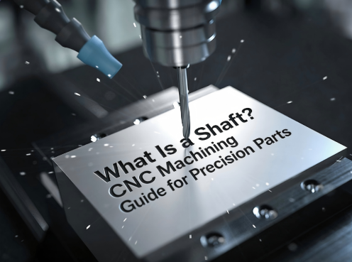
2.1 What Is a Shaft? Definition and Core Functions
A shaft is a cylindrical mechanical component used to support rotating parts, transmit torque, and bear loads. It is a core load-bearing element in mechanical transmission systems. It is typically installed inside equipment and works together with bearings, gears, pulleys, and couplings to achieve power transfer and motion conversion.
Functionally, a shaft usually performs at least four key roles.
2.1.1 Supporting Rotating Components
Many transmission elements cannot operate independently. They must be mounted on a shaft to rotate properly. The shaft provides the mounting reference and rotational center. If the shaft lacks sufficient rigidity, or if geometric tolerances are not well controlled, the rotating components may wobble, generate noise, or even fail.
2.1.2 Transmitting Torque and Rotary Motion
A shaft is not merely a support element. In many cases, it is itself a direct part of the power transmission path. Motor output, gear meshing, chain drive systems, and reduction mechanisms all rely on shafts. That means a shaft must offer not only dimensional accuracy, but also adequate torsional strength and fatigue life.
2.1.3 Bearing Radial and Axial Loads
In real working conditions, shafts often carry forces from multiple directions at once. At high rotational speed, even very small deviations are magnified. Once the load distribution becomes uneven, bearing life falls, vibration increases, and heat generation becomes much more noticeable.
2.1.4 Maintaining System Concentricity and Operational Stability
One of the key values of a shaft lies in the fact that it defines the rotational reference of the whole system. In many machines, the underlying logic of assembly accuracy ultimately comes down to one question: is the shaft truly accurate? If it is, the system runs smoothly. If it is even slightly off, problems begin to cascade.
2.2 Common Types of Shaft Parts
Shaft parts do not all follow one simple form. Different structures serve different functions, and they also require different machining priorities.
2.2.1 Plain Shafts
Plain shafts generally have a simple cylindrical form without distinct steps or complex added features. They are commonly used in guiding, supporting, and sliding-fit applications. Although the structure is simple, these shafts often demand very high standards for straightness, cylindricity, and surface roughness. Sometimes, the simplest-looking parts require the strongest fundamentals.
2.2.2 Stepped Shafts
Stepped shafts are the most widely used type. They feature multiple diameter sections and can simultaneously meet requirements for mounting, locating, supporting, and transmitting motion. Because the dimensional chain and concentric relationships between the steps are critical, machining must maintain continuity and consistency across multiple datum surfaces.
2.2.3 Special-Shaped Shafts and Eccentric Shafts
Special-shaped shafts and eccentric shafts are more function-driven. They are often used in special motion mechanisms, eccentric transmission systems, or complex machinery. These parts are significantly more difficult to machine. In addition to conventional turning, they frequently require milling, eccentric fixturing, or compound machining strategies.
For these asymmetric structures, machine axis configuration and interpolation capability can strongly influence toolpath planning, number of setups, and positional accuracy control. Especially when curved transitions, angled features, or multi-angle cutting are involved, whether a more advanced multi-axis solution is needed depends on the part’s actual complexity. That logic can be explored further in [30-Second Guide: 3-Axis vs 5-Axis CNC].
2.2.4 Splined Shafts and Threaded Shafts
Splined shafts are used to improve torque transmission and ensure a secure connection. Threaded shafts are commonly used in transmission, fastening, or positioning applications. These shafts must not only maintain the dimensional accuracy of the main body, but also ensure the form quality and fit performance of splines, threads, and other functional features.
2.2.5 Hollow Shafts
Hollow shafts are designed to reduce weight, save material, and improve dynamic performance. They are widely used in high-speed applications, lightweight systems, and assemblies requiring internal routing. Their main challenges lie in wall thickness control, rigidity balance, and deformation management during heat treatment. They may appear material-efficient, but they impose even higher process demands.
2.3 Core Accuracy Requirements for Shaft Parts
Shaft parts are difficult to manufacture not because their shapes are visually complex, but because their accuracy requirements are often concentrated and unforgiving.
2.3.1 Dimensional Tolerances
Outer diameter, overall length, step dimensions, and fit-section sizes are the most basic control items for shaft parts. Many precision shafts involve micron-level tolerance bands, especially at locations that mate with bearings, seals, or couplings. Even slight size deviations can immediately change assembly behavior.
2.3.2 Geometric Tolerances
Concentricity, roundness, cylindricity, perpendicularity, and radial runout are the most critical quality indicators for shaft parts. For high-speed rotating components, these characteristics are often even more important than ordinary linear dimensions. A shaft may be dimensionally correct, yet still be completely unacceptable in real use if runout exceeds specification.
2.3.3 Surface Quality
Shaft parts usually work in direct contact with bearings, bushings, seals, or rotating mating components, so surface roughness cannot be judged simply by whether it looks smooth. Ra value, tool marks, burr control, local scratches, and burn marks can all affect friction, wear, and service life.
2.3.4 Mechanical Properties
Many shafts must also meet requirements for hardness, wear resistance, fatigue performance, and torsional strength. In other words, a shaft must not only be accurate. It must also withstand load, rotate steadily, and last. That is why heat treatment and material selection are so important in shaft machining.
3. Pre-Machining Preparation for Precision Shaft Parts
3.1 Material Selection Must Match the Working Conditions
Material selection for shaft parts cannot be based on cost alone. It must be considered together with the operating environment, load conditions, service life requirements, and downstream processes. If the material is chosen incorrectly, no amount of precision later in machining can fully compensate for it.
3.1.1 Carbon Steel and Alloy Steel
Materials such as 45 steel and 40Cr are common choices for shaft parts. They offer high strength, stable overall performance, and good adaptability to heat treatment, making them suitable for general transmission shafts, support shafts, and mechanical structural shafts. For projects that need to balance performance and cost, these materials are often the first option.
3.1.2 Stainless Steel
Stainless steels such as 304 and 316 are better suited to corrosion-resistant applications, including food equipment, medical devices, coastal machinery, and outdoor systems. Their advantages are clear, but machinability is relatively less favorable. They tend to generate heat and build up on the cutting edge, which places greater demands on tooling and cutting parameter control. For related applications, see also [stainless steel CNC machining].
3.1.3 Aluminum Alloys
Alloys such as 6061 and 7075 are suitable for lightweight, high-speed, low-load, or weight-sensitive shaft parts. They machine well and support high productivity, but their wear resistance and rigidity are usually inferior to steel. As a result, they are not appropriate for every application. You can also explore [aluminum CNC machining] for lightweight precision parts.
3.1.4 Titanium Alloys and Copper Alloys
Titanium alloys are suitable for high-end lightweight, high-strength, and corrosion-resistant applications. Copper alloys are used where electrical conductivity, anti-friction behavior, or certain special working conditions are required. Both are more targeted material choices, come at a higher cost, and are more difficult to machine. They are usually selected for more demanding precision projects.
3.2 CNC Equipment and Workholding Selection
The machining quality of shaft parts depends heavily on whether the machine and fixturing strategy are appropriate. A poor equipment choice may not make the part impossible to produce, but it will make consistent precision much harder to achieve.
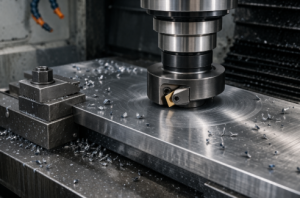
3.2.1 CNC Lathes
CNC lathes are the most fundamental and most essential machines for shaft parts. Both Swiss-type and conventional turning centers can cover a wide range of shaft machining needs. Small, long, high-precision shafts are often better suited to Swiss-type machines, while regular stepped shafts and medium-to-large shafts are more commonly machined on standard CNC lathes.
For more related processes, visit our [CNC turning services] page.
3.2.2 Turn-Mill Machines
For shaft parts with keyways, cross holes, threads, flat surfaces, eccentric features, or multiple compound features, turn-mill machines offer clear advantages. They reduce repeated setups, improve positional accuracy between features, and shorten process flow. The more complex the structure, the more valuable compound machining becomes.
If a part contains not only axial shaft features but also multi-angle milled surfaces, complex contours, or several spatial features that must be completed in one setup, then machine axis count stops being a simple specification difference and begins to directly affect lead time, cost, and accuracy outcome. For a deeper look at how 3-axis and 5-axis machines differ in such cases, see [30-Second Guide: 3-Axis vs 5-Axis CNC]. You may also want to review our [turn-mill machining services].
3.2.3 Workholding and Fixtures
Three-jaw chucks, four-jaw chucks, centers, collet systems, steady rests, and follow rests all directly influence machining stability. Shaft parts are especially vulnerable to eccentric clamping. Insufficient clamping force may cause slippage, while excessive force may leave damage or induce deformation. The part must be held securely, but it must also be held correctly.
3.2.4 Tool Selection
Carbide turning tools, grooving tools, threading tools, drills, reamers, and milling cutters must be selected according to material, part geometry, and surface requirements. Different materials demand different rake angles, clearance angles, nose radii, and coating types. Shaft machining may look turning-centered, but the tooling strategy is often highly refined.
3.3 Drawing Review and Process Planning
If the drawing is not fully understood, everything that follows can become wasted effort. Before machining shaft parts, the logic of the drawing must be fully absorbed rather than simply reading off a few dimensions.
3.3.1 Focus on Tolerances and Datums
Dimensional tolerances are only the surface layer. The real priorities are datum definitions, concentricity relationships, runout requirements, assembly fit sections, heat treatment notes, and surface finish specifications. Many problems in shaft machining are not caused by insufficient capability, but by misunderstanding the real priorities of the drawing at the start.
3.3.2 Plan a Logical Process Sequence
A typical flow may include rough turning, semi-finishing, finish turning, milling or drilling, heat treatment, and grinding or final precision finishing. The order cannot be arbitrary. In particular, stock allowance design before and after heat treatment, datum retention strategy, and protection of functional surfaces must all be planned in advance.
3.3.3 Set Cutting Parameters Carefully
Spindle speed, feed rate, depth of cut, and cooling strategy must balance efficiency, stability, and precision at the same time. Conservative parameters reduce productivity. Aggressive ones bring tool marks, distortion, and dimensional drift. Truly mature shaft machining does not push everything to the limit. It finds the most stable balance.
4. Core CNC Machining Process for Precision Shafts and the Key Points That Matter
4.1 Rough Machining: Fast Shaping, but Always Leave Room for Finishing
The purpose of rough machining is not to hit final tolerance. It is to remove most of the stock quickly, establish the basic profile, and create stable conditions for the finishing stages.
4.1.1 Form the Main Structure Efficiently
At this stage, the main outer diameters, steps, and end faces are roughed into shape. Efficiency matters, but it cannot be the only concern. If cutting stress is released too aggressively, distortion may appear immediately in later stages.
4.1.2 Control Cutting Stress
Shaft parts, especially slender shafts and thin-wall hollow shafts, are highly sensitive to internal stress. If rough turning uses too much depth of cut on one side, or if cutting heat becomes concentrated, the workpiece may bend, spring back, or continue drifting after heat treatment. Many quality issues are planted during roughing.
4.1.3 Leave a Proper Finishing Allowance
Finishing allowance is often left at roughly 0.2 mm to 0.5 mm, depending on the material, heat treatment route, and final accuracy requirement. Too little stock leaves no room for correction later. Too much stock increases cutting force and heat during finishing. The range looks simple, but in practice it depends heavily on experience.
4.2 Finish Machining: The Stage That Truly Determines Shaft Quality
If rough machining determines the outline, finish machining determines the quality. Most critical issues are ultimately decided here.
4.2.1 Tight Control of Dimensions and Geometric Tolerances
During finishing, the main focus is on outer diameter, mating step sections, concentricity, and runout. For multi-step shafts in particular, completing several critical sections in a single setup often makes it easier to preserve the overall concentric relationship than dividing them across multiple operations. One less setup means one less layer of risk.
4.2.2 Optimize Surface Quality
Surface roughness depends not only on tool sharpness, but also on feed rate, spindle speed, tool nose radius, coolant condition, and machine rigidity. Sometimes a shaft is dimensionally perfect but still shows visible tool marks, which means it is not truly acceptable. Mating and sealing surfaces do not forgive rough finish simply because the nominal size is correct.
For related tolerance topics, visit [tight tolerance machining] and [surface finish in CNC machining].
4.2.3 Use Compound Machining for Complex Shafts Whenever Possible
For shaft parts with milled slots, drilled holes, eccentric features, flat surfaces, or threaded combinations, integrated turn-mill machining is often better for controlling positional accuracy between features. The more the operations are scattered, the more setups are needed, and the greater the cumulative error. This is a major consideration in many complex shaft projects.
When a part evolves beyond a mainly rotational shaft into a combination of shaft body plus complex spatial geometry, whether 3-axis machining is sufficient or 5-axis machining is the better option depends on the accuracy target and fixturing strategy. At that point, it makes perfect sense to link readers to [30-Second Guide: 3-Axis vs 5-Axis CNC] for a broader understanding of how machine capability affects complex precision parts.
4.3 Secondary Operations and Heat Treatment: Keep Both Performance and Accuracy
Shaft parts are rarely finished once turning is done. In many projects, secondary operations and heat treatment are actually the stages that determine success or failure.
4.3.1 Heat Treatment Improves Overall Performance
Processes such as quenching and tempering, hardening, and carburizing can improve hardness, wear resistance, and fatigue performance in shaft parts. But heat treatment also introduces a risk of distortion. That means stock allowance planning, post-heat-treatment correction strategy, and follow-up finishing steps must all be considered in advance. Heat treatment cannot be treated as an afterthought.
4.3.2 Secondary Operations Complete the Functional Features
Keyways, cross holes, tapping, knurling, local flats, and cylindrical grinding usually fall into the category of secondary machining. These features may be local, but they often directly determine assembly fit and final function. Only when these details are done correctly is the shaft truly complete.
4.3.3 Stress Relief Helps Control Later Distortion
For certain high-precision shafts, long shafts, or stress-sensitive materials, stress relief treatment can release internal stress and reduce the risk of later distortion. It is not necessary for every project, but for higher-end shafts it is often well worth considering.
4.4 Surface Treatment: Not Decoration, but Functional Extension
Surface treatment on shaft parts usually serves three practical purposes: corrosion protection, wear resistance, and appearance improvement.
4.4.1 Common Surface Treatment Methods
Anodizing is suitable for aluminum alloy shafts. Zinc plating and black oxide are commonly used to improve corrosion resistance on steel shafts. Chrome plating can enhance surface wear resistance and corrosion performance. Polishing helps improve surface smoothness, while powder coating is more often used on certain exposed non-precision areas that need basic protection.
4.4.2 Surface Treatment Must Not Compromise Precision
This point is critical. The thickness of a surface treatment layer can directly affect fit dimensions on shaft parts. If that is not accounted for in advance, the finished size may fall out of tolerance after treatment. This is especially important for bearing seats, sealing surfaces, and precision fit sections. Treatment areas and masking strategy must be planned early.
5. Quality Inspection for CNC-Machined Shaft Parts
Shaft machining cannot rely only on machine stability, and it certainly cannot rely only on operator feel. Truly dependable quality control must be built on layered inspection.
5.1 Conventional Dimensional Inspection
Calipers, micrometers, and dial indicators are the most common basic tools for verifying diameter, length, step dimensions, and basic runout. They respond quickly and are well suited to first article checks and frequent in-process inspection.
5.2 Geometric Tolerance Inspection
Runout testers, V-block inspection with indicators, and CMM coordinate measuring machines are commonly used to inspect concentricity, circular runout, perpendicularity, and other key geometric characteristics. For high-precision shaft projects, standard handheld tools can only cover part of the requirement. More complex geometric relationships still demand higher-level inspection methods.
See also [CMM inspection for precision parts] and [quality control in CNC machining].
5.3 Surface Quality Inspection
Surface roughness testers can verify Ra values far more accurately than visual judgment alone. For fit areas and functional surfaces, this step cannot be skipped. A surface that looks shiny is not necessarily one that meets roughness requirements.
5.4 Performance Testing
Hardness testing, metallographic analysis, tensile testing, and other mechanical evaluations are used to confirm heat treatment results and material condition. These checks are especially important for shaft parts that operate long-term, require high wear resistance, or carry heavy loads. Looking only at dimensions while ignoring mechanical performance creates real risk.
6. Common Problems in Shaft CNC Machining and How to Solve Them
Shaft parts may appear structurally standard, but the problems they present are often concentrated and recurring. Once production moves into batch quantities, even very small deviations can escalate quickly.
6.1 Dimensional Out-of-Tolerance Conditions
Common causes include tool wear, thermal drift, inaccurate compensation values, batch variation in material, and datum shift during clamping. The solution is usually not a simple one-point fix. Tool condition, program compensation, machine thermal stability, and first article inspection frequency all need to be checked together. Dimensional error rarely comes from only one source.
6.2 Poor Concentricity or Excessive Runout
These issues are often related to the clamping method, center accuracy, center-hole quality, process order, and number of repeated setups. Improvement usually comes from better center consistency, fewer part reversals, improved datum retention, and increasing the number of critical sections completed in a single setup.
6.3 Rough Surface or Visible Tool Marks
Surface issues often stem from insufficient tool sharpness, unsuitable feed settings, mismatched spindle speed, inadequate machine rigidity, or unstable coolant performance. Sometimes the result improves noticeably just by changing to a more suitable finishing tool. Other times, the entire parameter set must be retuned rather than adjusting only one variable.
6.4 Workpiece Distortion
Slender shafts, hollow shafts, and heat-treated shafts are especially prone to this problem. Solutions may include reducing depth of cut, balancing cutting stress, adding stress relief treatment, optimizing clamping positions, and making better use of steady rests or follow rests. In many cases, distortion is not because the part was machined badly, but because the process did not respect the nature of the material.
6.5 Burrs and Scratches
Burrs are usually linked to tool edge condition, tool exit path, chip control, and secondary finishing practices. Scratches more often occur during transfer, fixturing, or inspection. Solving these issues requires not only machining-side control, but also better workpiece protection and handling discipline. A truly good shaft is not just good when it leaves the machine. It is still good when it reaches the customer.
7. Practical Considerations in Shaft Machining
7.1 Clamping and Positioning Must Be Stable
The last thing shaft machining can tolerate is eccentric clamping. Once the locating reference becomes unstable, every number that follows may lose meaning. This is especially true for multi-step shafts and slender shafts, where the clamping strategy must be validated in advance rather than improvised on the fly.
7.2 Tool Management Must Be Disciplined
Tool wear is one of the most common and most underestimated issues in batch shaft production. A first part that measures correctly does not mean the fiftieth one will. Regular inspection of tool edges, timely replacement of worn tools, and clearly defined tool life cycles are basic requirements for maintaining batch consistency.
7.3 Shop Environment Cannot Be Ignored
High-precision shaft machining is sensitive to temperature. In projects involving precision fit sections, long dimensions, or micron-level tolerances, thermal expansion and contraction can be enough to affect judgment. Machine warm-up stability, shop temperature control, and stable inspection conditions are all genuine quality variables.
7.4 Batch Production Requires Process Control
First article inspection, regular in-process checks, and final-piece verification form the basic logic of shaft production in volume. For precision machining projects aimed at batch-buying customers, final inspection alone is not nearly enough. The earlier process control begins, the lower the scrap rate, the more stable the delivery, and the more willing customers will be to place repeat orders.
8. Why Precision Shaft CNC Machining Tests a Supplier’s Overall Capability
At the beginning, many buyers assume shaft parts are standard components and therefore not especially complex. But once a project enters batch production, shaft parts often become the exact products that expose a supplier’s weaknesses most clearly. That is because they test not one isolated process, but the entire chain.
If the material is not properly understood, distortion is more likely later.
If the process route is poorly designed, concentricity becomes difficult to hold.
If heat treatment coordination is weak, dimensions begin to drift.
If the inspection system is not robust, batch consistency loses its foundation.
If surface protection is careless, damage may appear after shipment.
In addition, as many transmission components move toward lighter weight, combined structures, and multi-function integration, shaft parts are no longer always traditional turning-only components. Some projects now include side-milled features, irregular transition surfaces, angled holes, or complex interpolated features. In such cases, whether a supplier has a more flexible understanding of multi-axis machining can also influence project feasibility. On that point, it makes sense to direct procurement and engineering readers to [30-Second Guide: 3-Axis vs 5-Axis CNC] so they can more quickly understand how machine capability aligns with part complexity.
For a precision machining factory serving global manufacturers with reliable CNC services, shaft parts are a very typical capability test. If a supplier can manufacture shafts consistently and well, it usually means the company already has a relatively mature system in turning, compound machining, heat treatment coordination, quality control, and batch management.
9. Conclusion: In Precision Shaft CNC Machining, Quality Is Decided by Details
The structure of shaft parts is not visually dramatic, yet they are among the most critical components in precision machinery. They carry rotation, transmit power, and support the operational stability of the entire system. Machining a shaft may look like producing a cylindrical part, but in reality it means dealing with a full set of interrelated issues involving material choice, fixturing, cutting strategy, heat treatment, surface quality, geometric tolerance, and inspection logic.
When machining shafts, speed alone cannot be the goal.
Neither can short-term dimensional success.
Truly high-quality shaft CNC machining depends on correct material selection, clear process planning, controlled key tolerances, effective in-process inspection, and careful execution of every detail.
Only when all of these elements are handled properly can shaft parts truly achieve the required levels of precision, stability, and durability, allowing them to operate reliably over the long term in automotive systems, medical equipment, automation assemblies, construction machinery, and many kinds of high-end industrial equipment. For volume-buying customers, that kind of shaft is not just a qualified part. It is the result of a manufacturing process worth building a long-term partnership around.
If your shaft project also includes complex side features, irregular geometry, or multi-face compound structures, it is worth understanding [30-Second Guide: 3-Axis vs 5-Axis CNC] at the same time. Matching machine capability to part geometry early often helps avoid process risk and makes it easier to find the right balance among cost, precision, and lead time.
10. FAQ
What is a shaft in mechanical engineering?
A shaft is a cylindrical mechanical component used to support rotating parts, transmit torque, and carry radial or axial loads. It is a core element in power transmission systems and is widely used in automotive, automation, medical, and industrial machinery applications.
What are the most common types of shaft parts?
Common shaft types include plain shafts, stepped shafts, eccentric shafts, splined shafts, threaded shafts, and hollow shafts. Each type serves a different mechanical function and requires a different CNC machining strategy.
What materials are commonly used for precision shaft parts?
Precision shaft parts are commonly made from carbon steel, alloy steel, stainless steel, aluminum alloys, titanium alloys, and copper alloys. The right choice depends on strength, wear resistance, corrosion resistance, weight, and application requirements.
What is the main CNC machining process for shaft parts?
The main process usually includes rough turning, semi-finishing, finish turning, milling or drilling if needed, heat treatment, and final grinding or precision finishing. The exact route depends on geometry, tolerance, and material condition.
Why are concentricity and runout important in shaft machining?
Concentricity and runout directly affect rotational stability, assembly accuracy, vibration level, and service life. Even if the diameter is within tolerance, excessive runout can still make a shaft unusable in real applications.
How are precision shaft parts inspected?
Precision shaft parts are typically inspected using calipers, micrometers, dial indicators, runout testers, surface roughness testers, hardness testers, and CMM equipment. Different tools are used for dimensional checks, geometric tolerance verification, and material performance validation.
What are the common problems in shaft CNC machining?
Common issues include dimensional deviation, excessive runout, poor surface finish, thermal deformation, burrs, and scratches. These are often caused by tool wear, unstable workholding, process design problems, or insufficient inspection control.
When should 3-axis or 5-axis CNC be considered for shaft parts?
Standard shaft parts are often produced mainly by CNC turning or turn-mill machining, but when a shaft includes angled features, side milling, compound surfaces, or complex spatial geometry, it may be useful to evaluate different machining approaches.